

Recent posts
#1
Client Projects & Tips – Tube Chassis / Re: Scope creep '69 Cougar
Last post by Ryan Kennedy - May 29, 2026, 02:52 PMThe diff cooler was a really neat project. Areas in direct airflow at the front of the car being taken up already made for some thinking on how to feed the cooler core. Mounting a core out of airflow and then adding a fan is ok, but if I could figure out a way to bring air into the core... The first obvious place seen in racing would be NACA ducts in the window area. The qtr windows on the cougar are of decent size but still not big enough for a proper duct much less two, so that was out. The package tray area is sealed to the base of the rear windshield so simply putting the core in the package tray and relying on pressure to build was a possibility, but not a for sure. This would mean the exhaust from the core just goes under the package tray in the trunk area - whos to say the pressure building under the package tray isn't to same or more than the pressure above? Nope.
The bottom of the car is mostly flat, what if I brought air from under the car? Plenty of volume under there, and flow being king, lets give it a whirl!
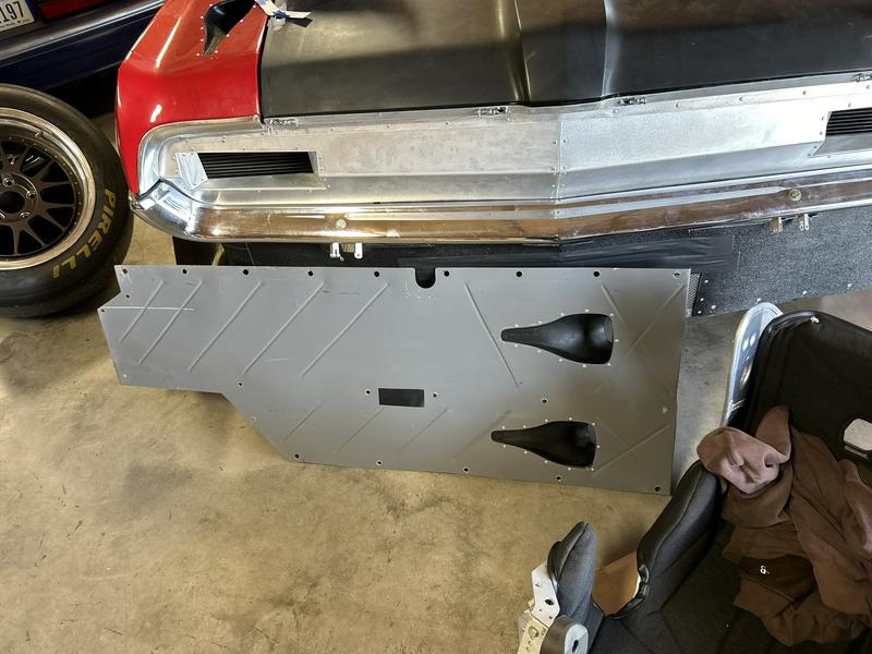
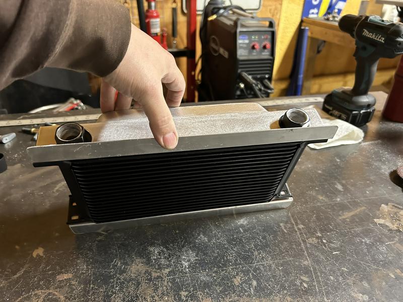
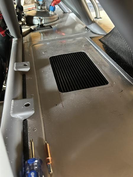
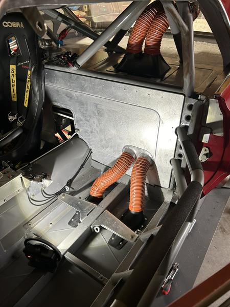
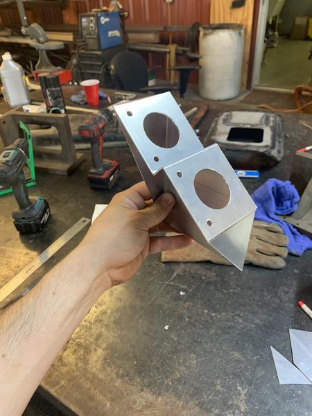
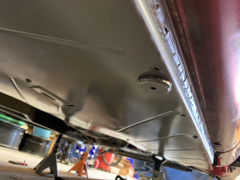
Despite the very crowded picture, here's the driver side floor with NACA ducts installed. I don't have pictures of the ducts without the rest of the path so this will do for now. Next was the core, and how to get two hoses to feed the core and seal.
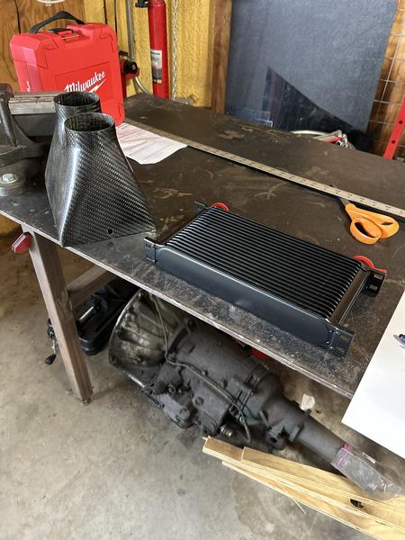
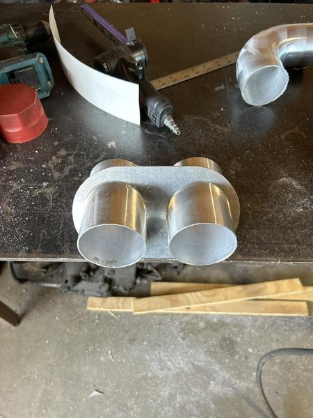
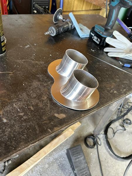
I feel like a broken record - more used race parts . Picked up a couple carbon ducts with the size inlets I wanted and got to work on how to hold it to the core.
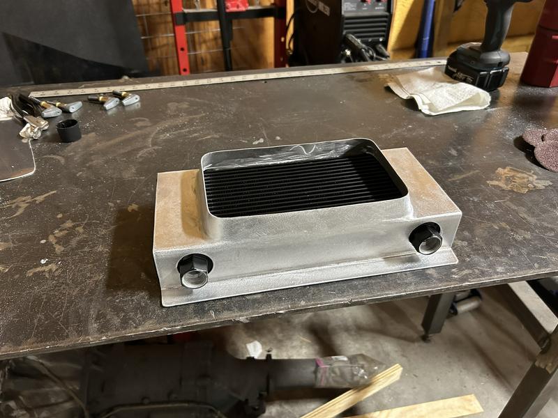
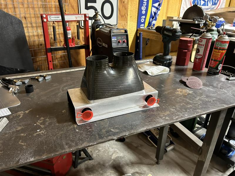
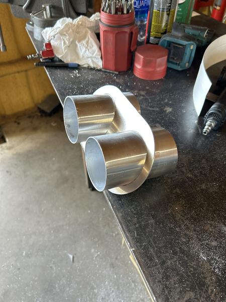
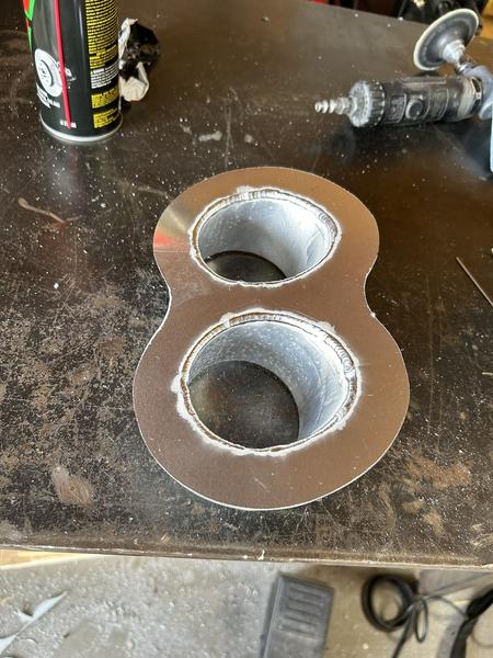
I was dabbling into welded sheet metal work compared to what I'd done in the past which was all rivetted together, and it turned out really well. Now it starts getting cool. The cooler/duct assembly mounts to the bottom of the package tray since the air is coming from the floor under the driver seat.
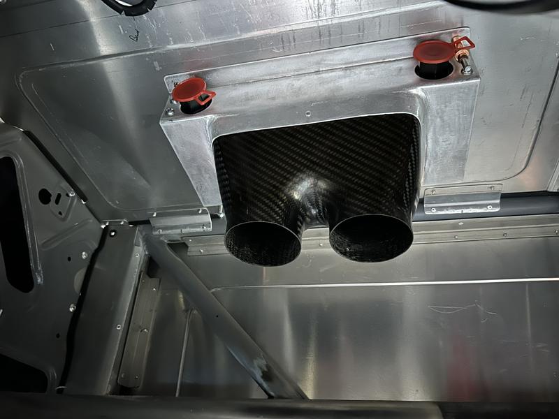
In the next picture you can see the outlet duct on top of the package tray with the cooler core removed. Again, changing back to hoses for a clean exit
Now we have an inlet and an outlet for the cooler core, but still no path from the NACA ducts.
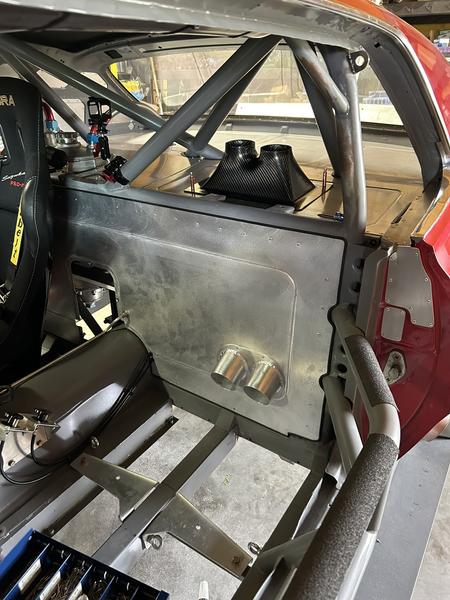
And on to the exit. I wish I would have made more of a teardrop shape, but it still turned out really nice.
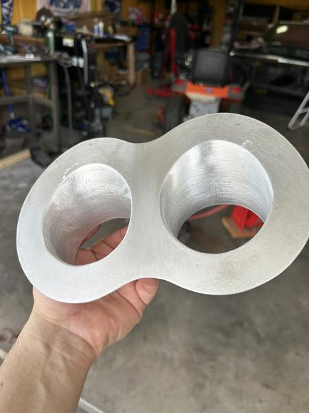
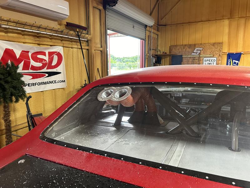
Now the path is completed!
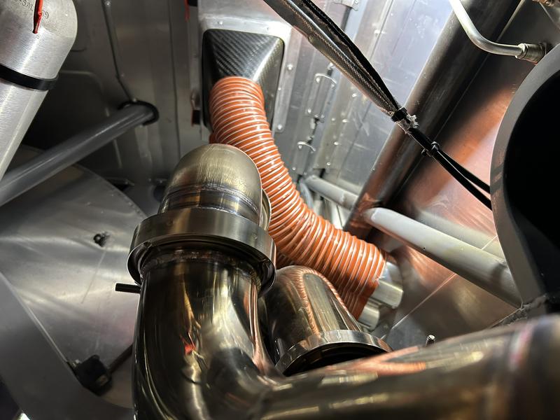
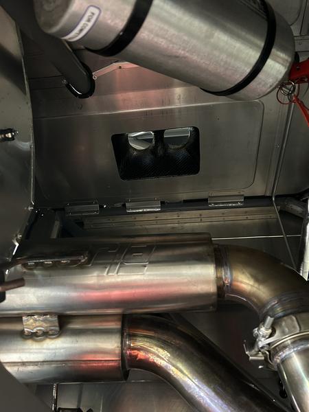
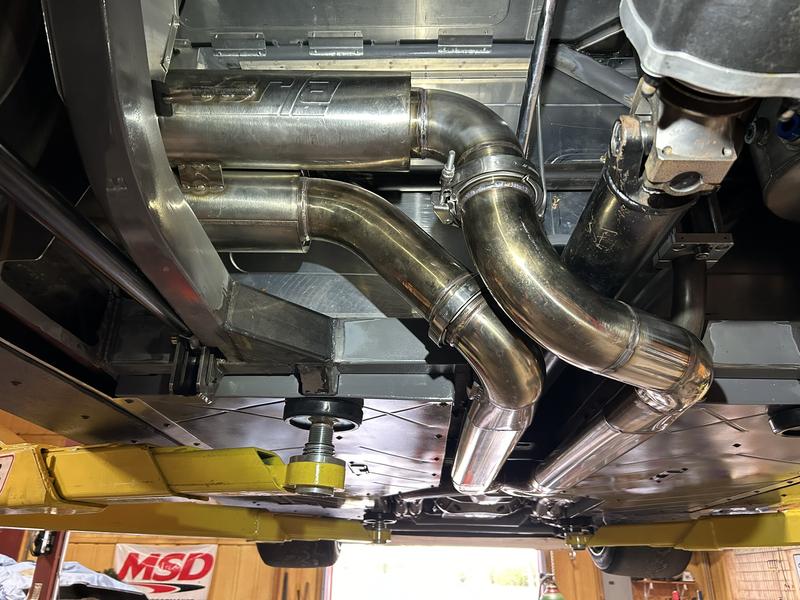
The ducting underneath is close-ish to the exhaust, but that's just how it has to be. Given the volume I'm hoping will be coming through the ducts, I don't think its going to matter. If the cooler is less effective than I'm hoping (if even needed), the first thign I'd likely try would be a simple heat shield in this area for the tubing.
The location for the core and ultimately the outlet was chosen more to prevent obstruction of rear view for me when driving. Could have gotten further away from the exhaust, but my already limited view behind would have been basically eliminated. Now instead of wiring up a cooler fan, I'd be wiring up a rear view camera.
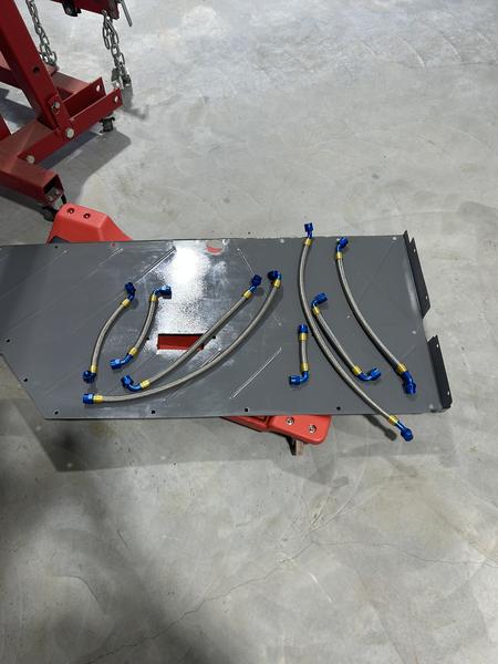
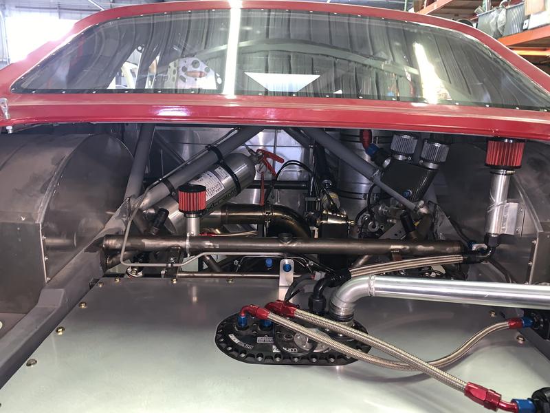
The plumbing side of things is pretty basic. 100 Micron filter on the inlet side of the belt driven Johnson cooler pump, and that's about all there is going on other than a lot of hoses! The internal pumps are really neat, my gearset doesn't have the provisions for it.
The bottom of the car is mostly flat, what if I brought air from under the car? Plenty of volume under there, and flow being king, lets give it a whirl!
Despite the very crowded picture, here's the driver side floor with NACA ducts installed. I don't have pictures of the ducts without the rest of the path so this will do for now. Next was the core, and how to get two hoses to feed the core and seal.
I feel like a broken record - more used race parts
. Picked up a couple carbon ducts with the size inlets I wanted and got to work on how to hold it to the core. I was dabbling into welded sheet metal work compared to what I'd done in the past which was all rivetted together, and it turned out really well. Now it starts getting cool. The cooler/duct assembly mounts to the bottom of the package tray since the air is coming from the floor under the driver seat.
In the next picture you can see the outlet duct on top of the package tray with the cooler core removed. Again, changing back to hoses for a clean exit
Now we have an inlet and an outlet for the cooler core, but still no path from the NACA ducts.
And on to the exit. I wish I would have made more of a teardrop shape, but it still turned out really nice.
Now the path is completed!
The ducting underneath is close-ish to the exhaust, but that's just how it has to be. Given the volume I'm hoping will be coming through the ducts, I don't think its going to matter. If the cooler is less effective than I'm hoping (if even needed), the first thign I'd likely try would be a simple heat shield in this area for the tubing.
The location for the core and ultimately the outlet was chosen more to prevent obstruction of rear view for me when driving. Could have gotten further away from the exhaust, but my already limited view behind would have been basically eliminated. Now instead of wiring up a cooler fan, I'd be wiring up a rear view camera.
The plumbing side of things is pretty basic. 100 Micron filter on the inlet side of the belt driven Johnson cooler pump, and that's about all there is going on other than a lot of hoses! The internal pumps are really neat, my gearset doesn't have the provisions for it.
#2
Client Projects & Tips – Tube Chassis / Re: Scope creep '69 Cougar
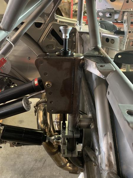
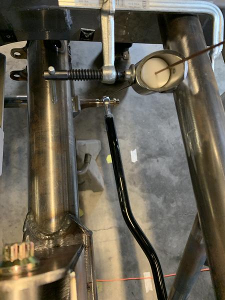
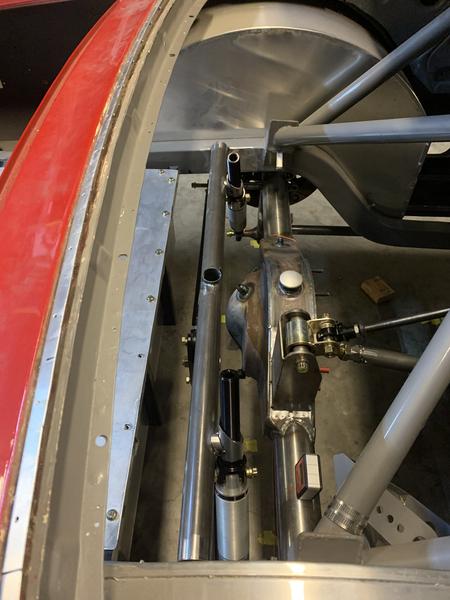
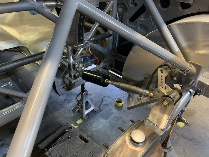
Last post by Ryan Kennedy - May 19, 2026, 11:44 AMOne of the really cool things about the decoupled 3-link is the ease of adjustment. Of course this also means, to take advantage of what the suspension offers, you have to make changes! Already talked about the RC adjustment in the trunk, so on to Anti-squat adjustment. The J-bar bracing is designed to use a jacking screw that passes into the drivers compartment.
Something maybe Ron can shed some light on - how much adjustment to the AS can be made before re-shimming for damper preload and pinion angle must occur?
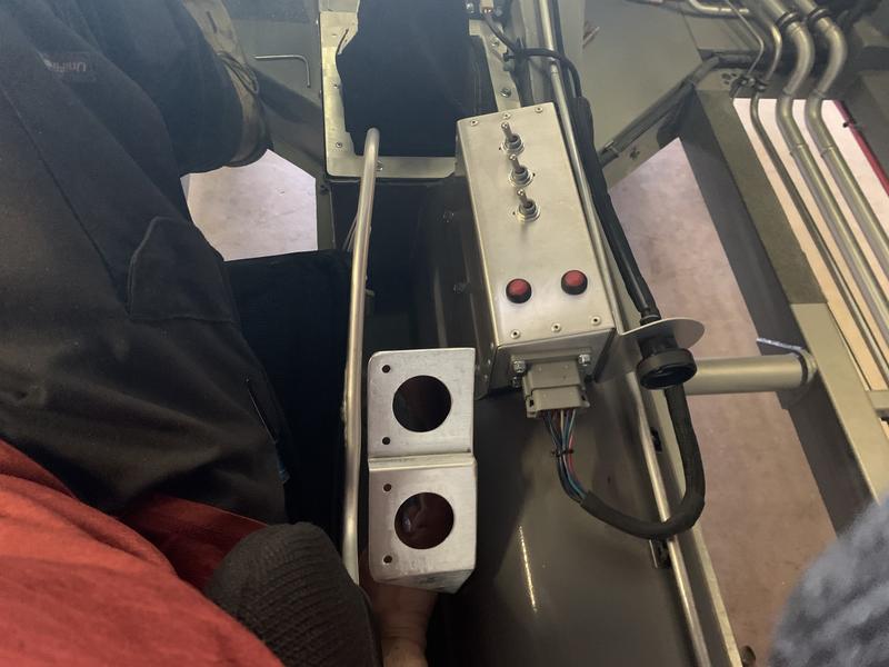
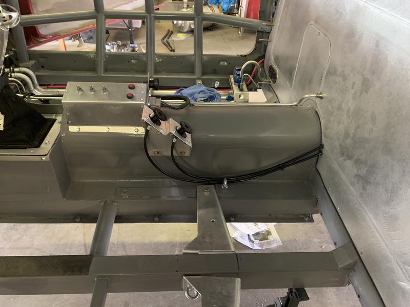
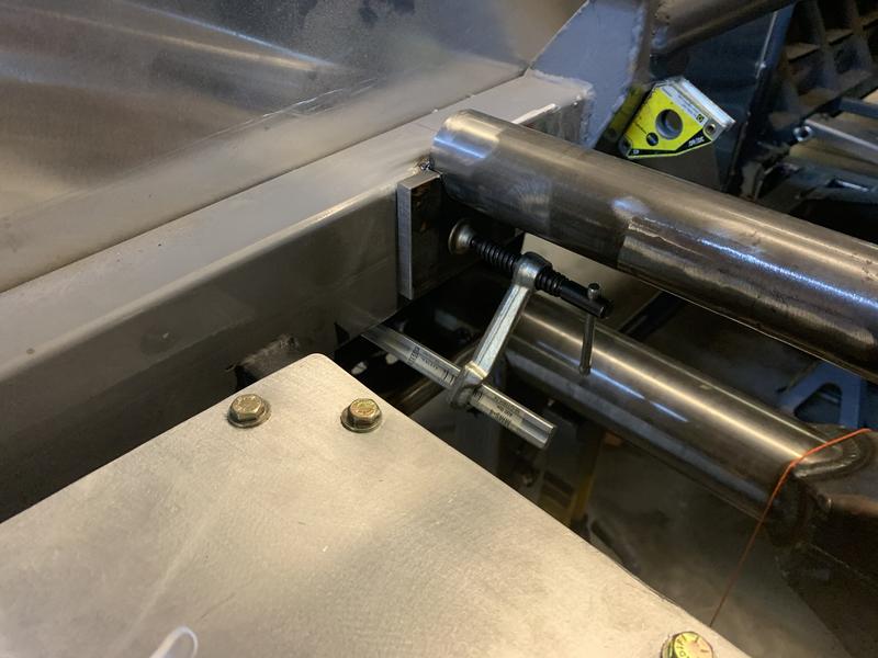
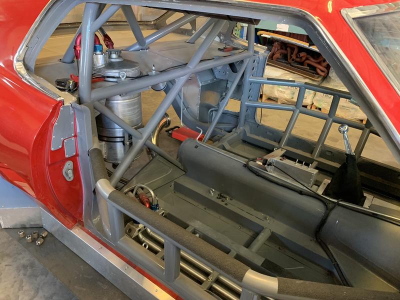
Which brings us to the next item, the decel link which is a double adjustable damper and also plays a role in accel control. Provided with the setup are remote adjustment cables/knobs to be mounted for driver adjustment. Rebound for accel control and compression for braking control. Made a bracket to mount next to the driver seat for these two adjustments.
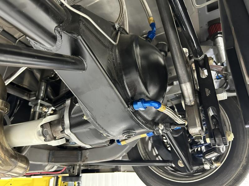
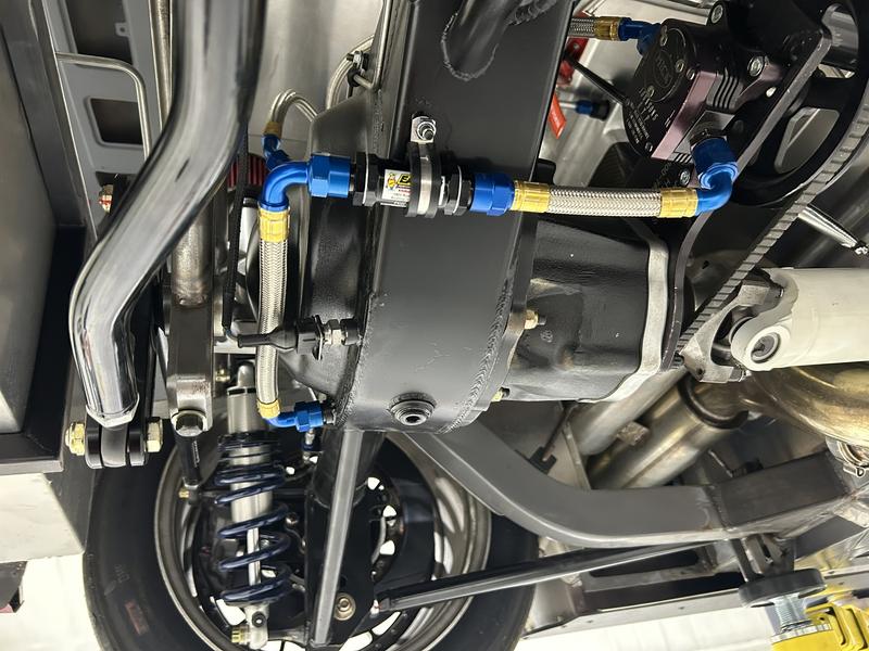
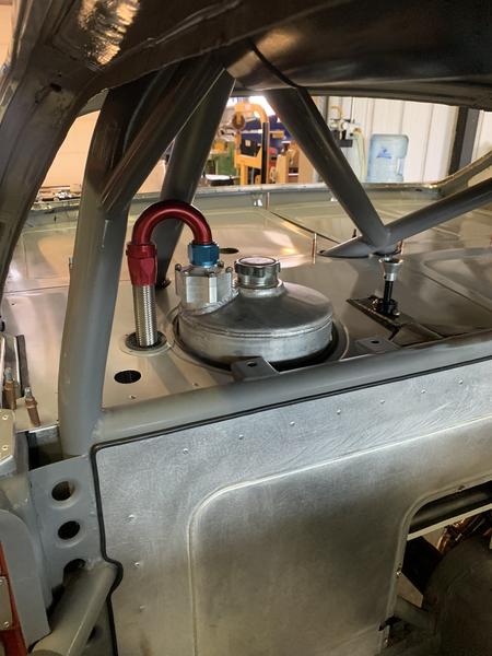
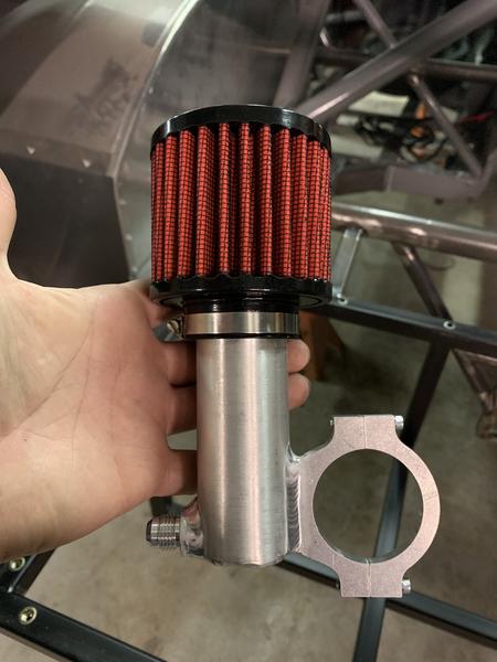
Made a diff breather similar to the fuel cell but without baffles. There's a lot going on, but here's a pic all assembled.
And of course, as is tradition, another exhaust modification....ugh.
That kinda wraps up the decoupled 3-link! I'm very excited to finally getting back to the car in the next couple weeks and do some more testing.
As I mentioned in the last post, I ended up making a diff cooler that I may now not need, but its there if I do need it! Ill go over that next
Something maybe Ron can shed some light on - how much adjustment to the AS can be made before re-shimming for damper preload and pinion angle must occur?
Which brings us to the next item, the decel link which is a double adjustable damper and also plays a role in accel control. Provided with the setup are remote adjustment cables/knobs to be mounted for driver adjustment. Rebound for accel control and compression for braking control. Made a bracket to mount next to the driver seat for these two adjustments.
Made a diff breather similar to the fuel cell but without baffles. There's a lot going on, but here's a pic all assembled.
And of course, as is tradition, another exhaust modification....ugh.
That kinda wraps up the decoupled 3-link! I'm very excited to finally getting back to the car in the next couple weeks and do some more testing.
As I mentioned in the last post, I ended up making a diff cooler that I may now not need, but its there if I do need it! Ill go over that next
#3
Client Projects & Tips – Tube Chassis / Re: Scope creep '69 Cougar
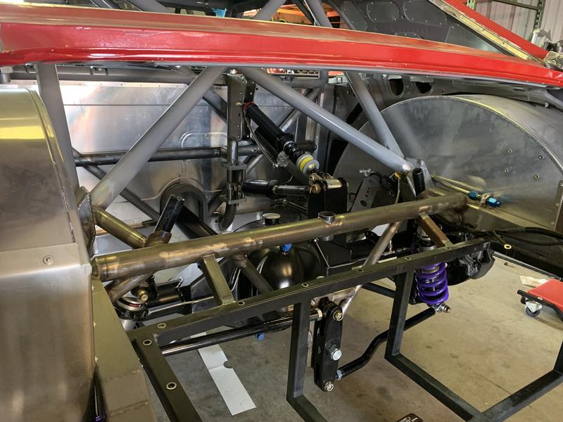
Last post by Ryan Kennedy - May 16, 2026, 02:06 PMNow it was time for the lateral locating device. Watts or panhard bar. Having read some of Ron's tech articles I understood some of the advantages that the PB can offer over the watts link, such as ability to plant one tire harder than the other depending on how the bar is setup. The debate really became what would offer the best results with the labor available to me at the track. I am the labor available at the track. Just me. This made the watts link my choice - quick and reliable changes, with only one point of adjustment.
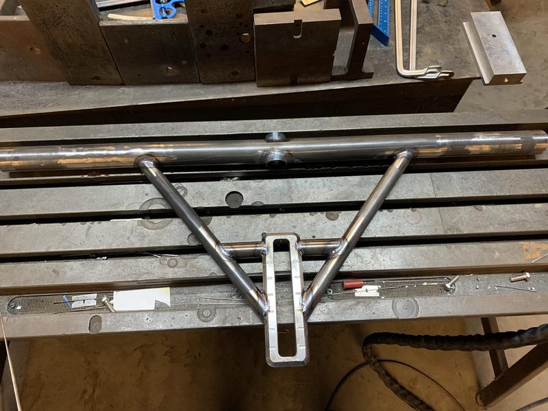
Every chassis being different, Ron provided a RC range he wants the setup to be able to achieve, and I built the watts frame accordingly. Notice the tube pass through in the crossmember. This allows for quick adjustment of the watts height. Still have to loosen the nut on the propeller but its so quick.
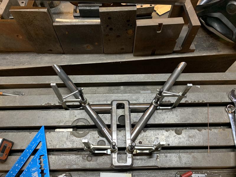
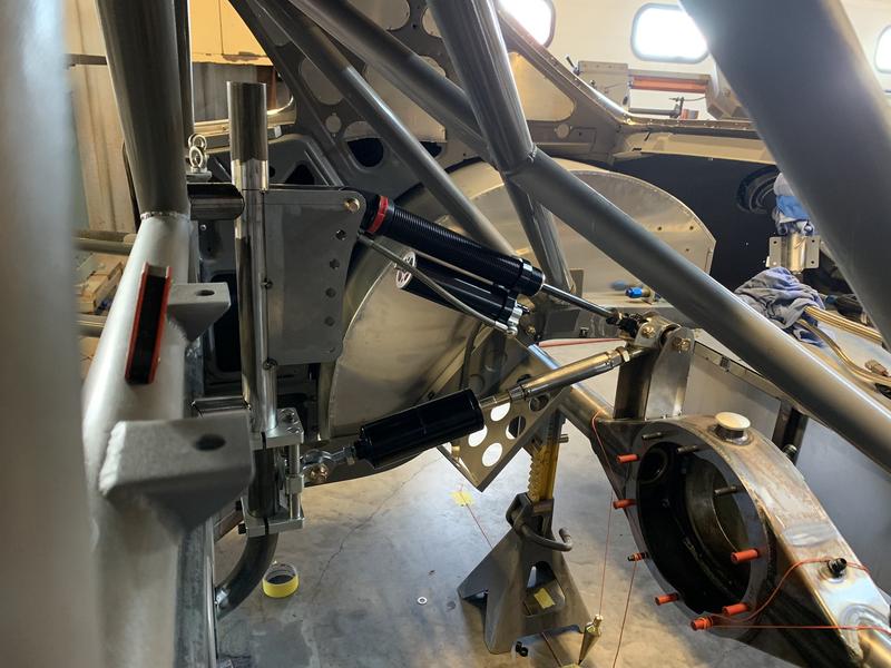
This is also where another challenge presented itself. Jacking screws and associated fabrication parts are supplied with the kit to establish the angles of the shocks, but its up to you to locate them correctly. The shocks need to be at the lowest angle of misalignment with the mounts at ride height, and that's where the problem presents itself. You now have a shock that doesn't wish to be compressed at all, that you need to hold in place on brackets that aren't held to anything themselves.
Went through several trial and error moments with angle finders and cutting tacks until a friend of mine suggested this little guy.
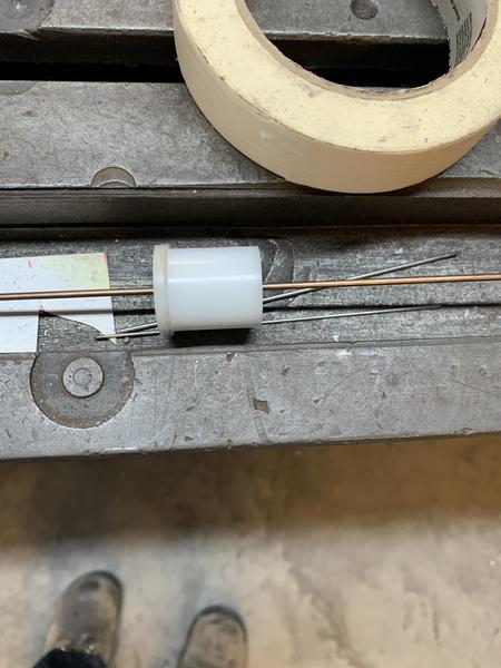
Simplest little piece of delrin and a 3/32 welding rod. Now how to hold the crossmember in place which moving things around. Being round tube, and a little bit weighty, its a real pain. Ron does offer a setup tool for this, but I didn't have it. Another method would be to obtain swage tubes and rod ends at the correct length the shock would be at ride height. There's options, but the little delrin guy came in clutch.
Again with the simplest thing I could think of. 1-3/4 hole saw in a piece of plate, then cut it in half. Now I had something to hold the tube in exact place that I could clamp and move around.
You're probably asking why the crossmember tube is above the frame rail if I had control over the height of the watts link adjuster, and the answer is the upper shock mounts. Despite being 100% the way I'd do it again, the jacking screws do add some height to the overall setup. Having only given myself enough adjustment to run one height tire my first go around, I didn't want to limit my options. With the jacking screws I can accommodate a 710mm tall slick. Another note to think about with the decoupled setup is the movement of the axle under acceleration. There's a coil spring inside the black canister that compresses and makes the axle move rearward. The location of the watts link has to be able to handle this movement.
Now that the location of the crossmember is set, how to tie the crossmember and shock mounts into the rest of the chassis.
The square tubes coming off the fuel cell cage had to be reintroduced since I still need an ARB. Big milestone getting most things welded in.
Yes, those last couple pictures sprung ahead a little bit to the rear closeout being done, so lets check that out. The original closeouts were really neat being between all the tubes but now with the extra harness bar, I was out of desire to make that again, so I went basic. Still needed to add some complication, but not nearly as much, in the form of an access panel to make in car adjustments to the accel link. Yes, there is a jack screw on the front of the accel link, but if movement beyond the jack screws capability is needed, the access is nice.
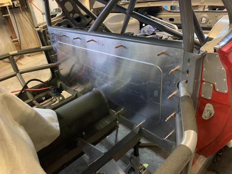
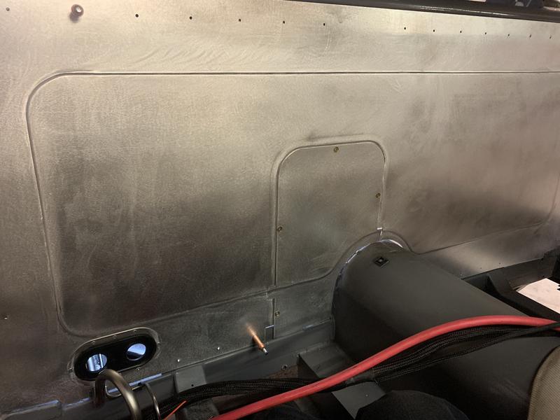
Some 1/4 turn fasteners made for a really nice panel.
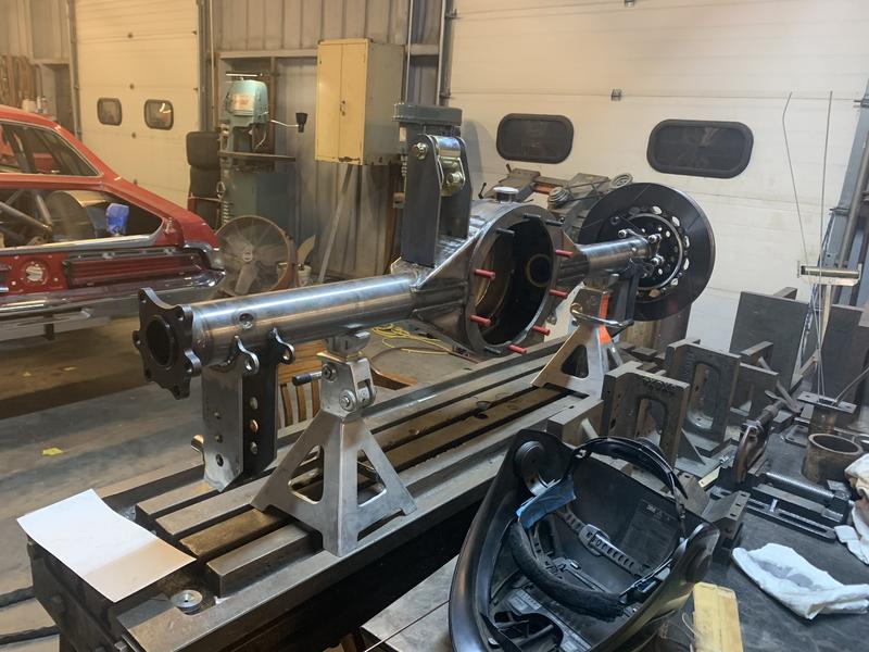
Somewhere in here, it was time to assemble an axle! Due to their robust nature a locker had already been chosen, but I needed to make sure it had the proper springs in it. I chose 40# springs just in case I ever decided to compete in class that had a treadwear rule. Since I'm never going to see a super speedway, there's no downside to going light on the springs.
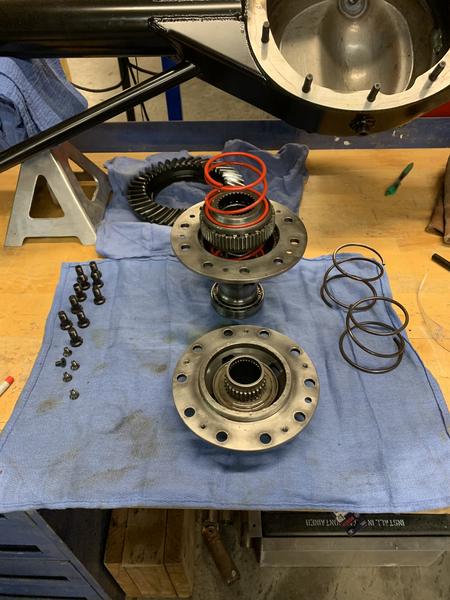
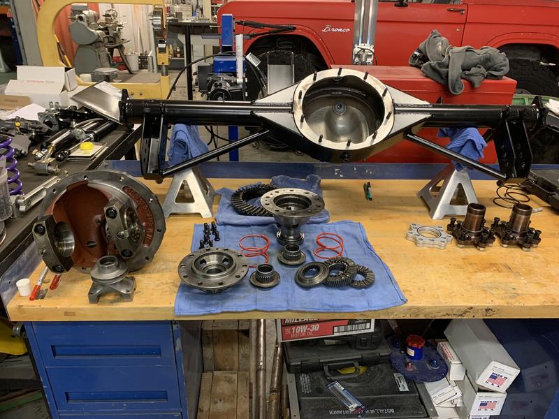
Re-springing the lockers is easy, but not without its challenges. I did end up having to trim a decent amount off the new springs to get the diff to reliably unlock. Luckily, and this is a BIG luckily, Strange oops'd on one of my axles, giving me a spare that I could turn into a setup tool. They did make it right without an additional cost to me, by the way. I tested unlocking on the bench as well as once I got the setup in the car. Testing the diff on the bench is the only way to go, imo. Especially considering how difficult an iron 3rd member is to manipulate by yourself when its under the car.
One more item on 9" 3rd members and then I have to roll. Finish up the decoupled install on the next post - I'm using a Mark Williams 3rd member. Not the lightest of items but the quality is there, and Scot Rods Garage made me a killer deal on the whole 3rd member. Being more of a heavy duty 3rd member it has a load bolt location on the side of the case about an inch below where the factory fill hole is. Due to this there is NO FILL HOLE! W...T....F. I, never having been into drag racing or off road stuff never knew that such a thing existed. First time with this setup on track the diff was running really hot. Being a locker and not having any clutches I wasn't too concerned running it hot during testing, but knew a solution was needed, as 300F is not sustainable. Luckily, I already had ports welded into the housing for a cooler should it be needed....still don't know if it's needed, but its there lol!
Learning later that what I thought was a fill plug was actually a load bolt hole, my axle was a bit underfilled....face meet palm. Now I have a really neat cooler setup that I may not need. I'll go over it after the 3-link install because I'm very proud of it. So, beware of what you're getting when you buy aftermarket 3rd members - they may have qualities that you're not familiar with.
Every chassis being different, Ron provided a RC range he wants the setup to be able to achieve, and I built the watts frame accordingly. Notice the tube pass through in the crossmember. This allows for quick adjustment of the watts height. Still have to loosen the nut on the propeller but its so quick.
This is also where another challenge presented itself. Jacking screws and associated fabrication parts are supplied with the kit to establish the angles of the shocks, but its up to you to locate them correctly. The shocks need to be at the lowest angle of misalignment with the mounts at ride height, and that's where the problem presents itself. You now have a shock that doesn't wish to be compressed at all, that you need to hold in place on brackets that aren't held to anything themselves.
Went through several trial and error moments with angle finders and cutting tacks until a friend of mine suggested this little guy.
Simplest little piece of delrin and a 3/32 welding rod. Now how to hold the crossmember in place which moving things around. Being round tube, and a little bit weighty, its a real pain. Ron does offer a setup tool for this, but I didn't have it. Another method would be to obtain swage tubes and rod ends at the correct length the shock would be at ride height. There's options, but the little delrin guy came in clutch.
Again with the simplest thing I could think of. 1-3/4 hole saw in a piece of plate, then cut it in half. Now I had something to hold the tube in exact place that I could clamp and move around.
You're probably asking why the crossmember tube is above the frame rail if I had control over the height of the watts link adjuster, and the answer is the upper shock mounts. Despite being 100% the way I'd do it again, the jacking screws do add some height to the overall setup. Having only given myself enough adjustment to run one height tire my first go around, I didn't want to limit my options. With the jacking screws I can accommodate a 710mm tall slick. Another note to think about with the decoupled setup is the movement of the axle under acceleration. There's a coil spring inside the black canister that compresses and makes the axle move rearward. The location of the watts link has to be able to handle this movement.
Now that the location of the crossmember is set, how to tie the crossmember and shock mounts into the rest of the chassis.
The square tubes coming off the fuel cell cage had to be reintroduced since I still need an ARB. Big milestone getting most things welded in.
Yes, those last couple pictures sprung ahead a little bit to the rear closeout being done, so lets check that out. The original closeouts were really neat being between all the tubes but now with the extra harness bar, I was out of desire to make that again, so I went basic. Still needed to add some complication, but not nearly as much, in the form of an access panel to make in car adjustments to the accel link. Yes, there is a jack screw on the front of the accel link, but if movement beyond the jack screws capability is needed, the access is nice.
Some 1/4 turn fasteners made for a really nice panel.
Somewhere in here, it was time to assemble an axle! Due to their robust nature a locker had already been chosen, but I needed to make sure it had the proper springs in it. I chose 40# springs just in case I ever decided to compete in class that had a treadwear rule. Since I'm never going to see a super speedway, there's no downside to going light on the springs.
Re-springing the lockers is easy, but not without its challenges. I did end up having to trim a decent amount off the new springs to get the diff to reliably unlock. Luckily, and this is a BIG luckily, Strange oops'd on one of my axles, giving me a spare that I could turn into a setup tool. They did make it right without an additional cost to me, by the way. I tested unlocking on the bench as well as once I got the setup in the car. Testing the diff on the bench is the only way to go, imo. Especially considering how difficult an iron 3rd member is to manipulate by yourself when its under the car.
One more item on 9" 3rd members and then I have to roll. Finish up the decoupled install on the next post - I'm using a Mark Williams 3rd member. Not the lightest of items but the quality is there, and Scot Rods Garage made me a killer deal on the whole 3rd member. Being more of a heavy duty 3rd member it has a load bolt location on the side of the case about an inch below where the factory fill hole is. Due to this there is NO FILL HOLE! W...T....F. I, never having been into drag racing or off road stuff never knew that such a thing existed. First time with this setup on track the diff was running really hot. Being a locker and not having any clutches I wasn't too concerned running it hot during testing, but knew a solution was needed, as 300F is not sustainable. Luckily, I already had ports welded into the housing for a cooler should it be needed....still don't know if it's needed, but its there lol!
Learning later that what I thought was a fill plug was actually a load bolt hole, my axle was a bit underfilled....face meet palm. Now I have a really neat cooler setup that I may not need. I'll go over it after the 3-link install because I'm very proud of it. So, beware of what you're getting when you buy aftermarket 3rd members - they may have qualities that you're not familiar with.
#4
Client Projects & Tips – Muscle Cars / Re: Brakes
Last post by PJ Runnells - May 13, 2026, 05:29 PMHey Ron, also wanted to ask what about stop tech brake pads. Are brake pads going to be available through other sources.
Thanks, PJ
Thanks, PJ
#5
Client Projects & Tips – Tube Chassis / Re: Scope creep '69 Cougar
Last post by Ryan Kennedy - May 11, 2026, 01:47 AMThanks, Ron! Very excited about the setup even though I haven't gotten much testing on it so far.
Back to the question at the end of the last post - where's the Torque Arm?! At this point I had to make a decision - make mounts to reinstall the TA from the 8.8" on the 9" axle or accept that this is a sign that a different rear suspension setup is meant to be in the car. Can't ignore signs from on high, now can we?
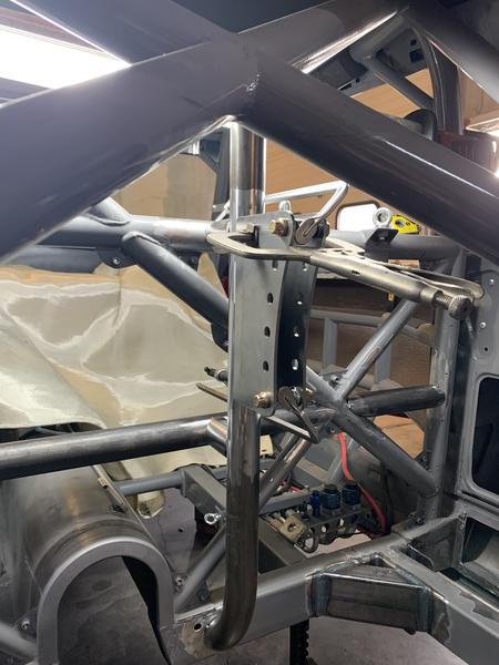
I had my eye on one of Ron's decoupled 3-link setups for a while, so it was time to see what needed to be done for the Cougar to have one. One of the biggest hurdles installing the 3-link was the second "harness bar" that needed to be added. Due to the forces being applied in both acceleration and braking, more support for the J-bar is needed.
Here we go again. Disassemble the assembled
Right around this time, what should arrive?

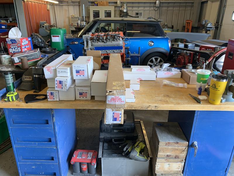
Soooo many cool things in these boxes. All organized with the respective hardware and Ron had already sent me an email with takeoff points and fabrication guidelines. Back to the second harness bar!
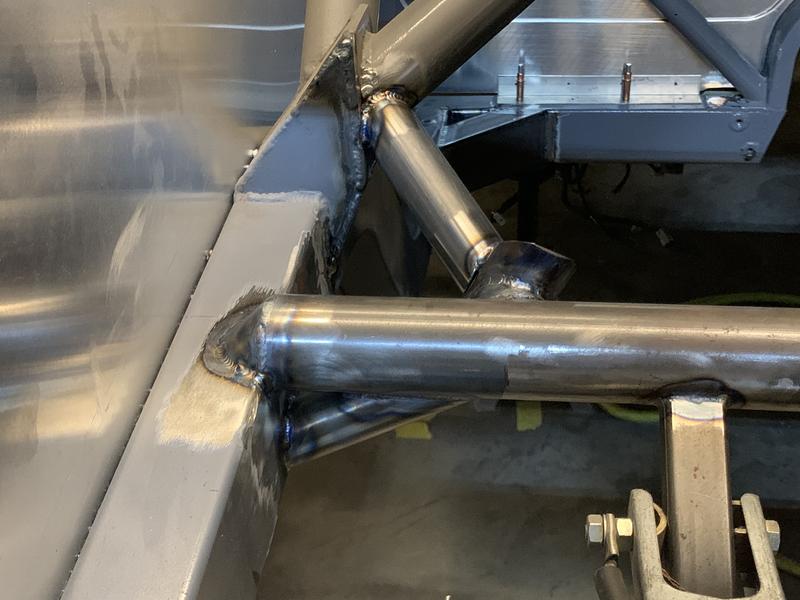
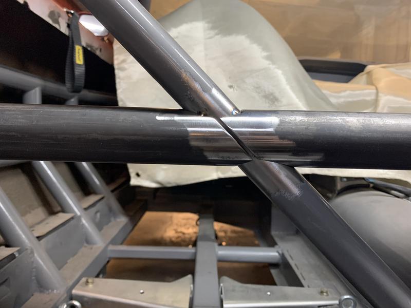
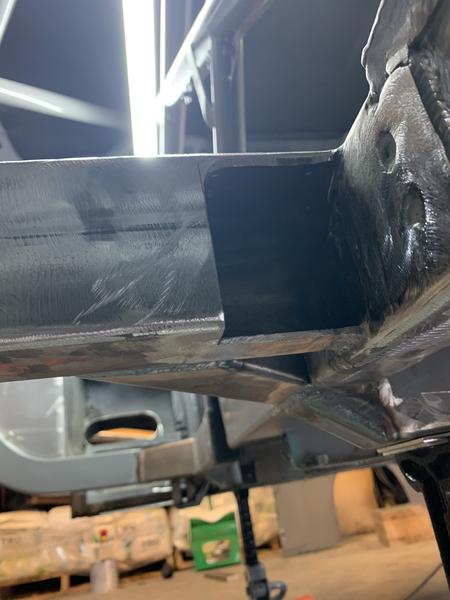
The biggest issue was the 1-1/4" triangulation of the main crossmember. There was no way I was going to risk movement in the chassis at this point so I decided to make my life more difficult and install the 1-3/4" around the 1-1/4". Took a lot of fitting and trimming to achieve the 3-piece tube to make all this happen, but it turned out really well.
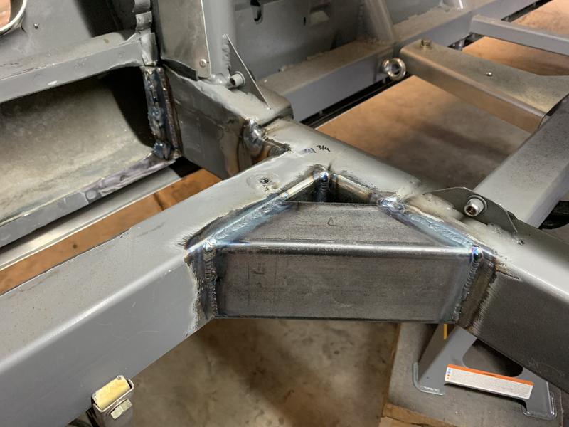
Also in the picture are 2x3 tube gussets where the rear rails meets the main crossmember. Gussets like these were originally on the outside, and the lower control arm was on the inside of the frame rail. Ron had specified the control arm be on the outside of the frame rail so this required some changes. I like this configuration much better.
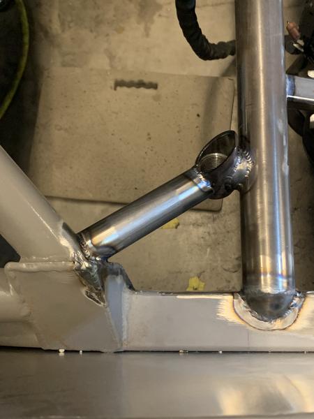
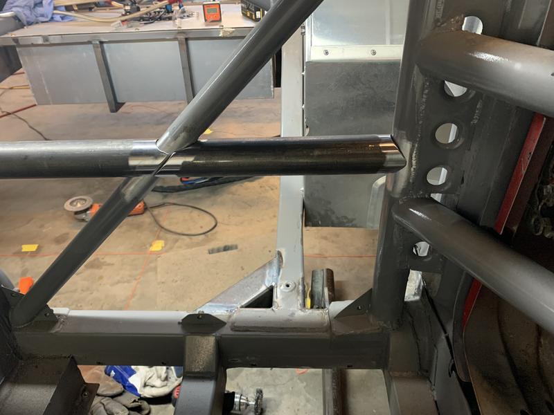
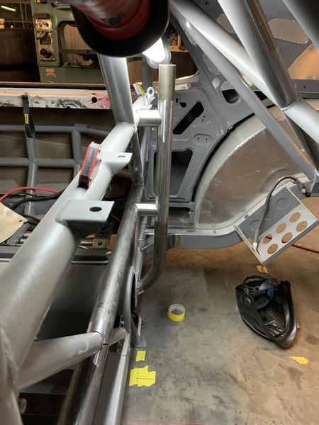
Next were the slotted front LCA mounts. These presented a real challenge. As with most things on the car, the changes I was making and the hardware I was wanting to incorporate wasn't part of the original vision so I had to get creating in some areas. The front LCA mount was one of them.
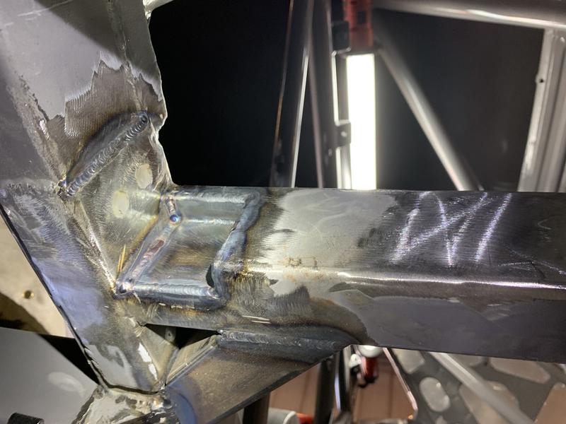
The pocket in the frame rail that you see had to be made so the the nut, and more importantly, a wrench could be fit in to tighten the LCA bolt. As much of a PITA as this looks, it turned out great. An open end wrench can be fed into the slot with the nut if necessary and its essentially captured during installation and tightening.
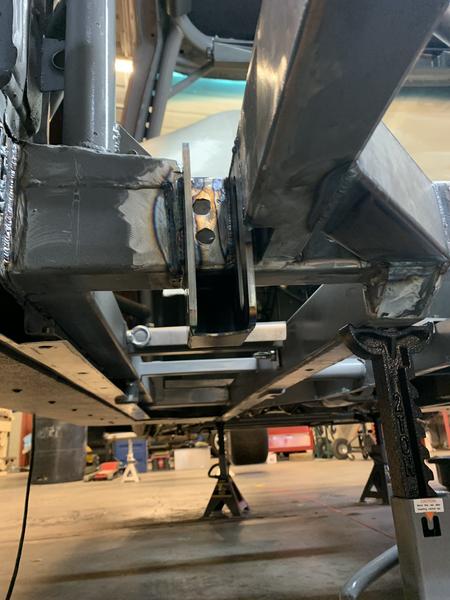
Not in these pictures, but just a cool thing Ron does with his DIY packages is include spacers to be used during welding. Bolts in place with an additional shim he supplies to allow for heat distortion and paint after install. I had no problems with double sheer mounting points being too tight after welding.
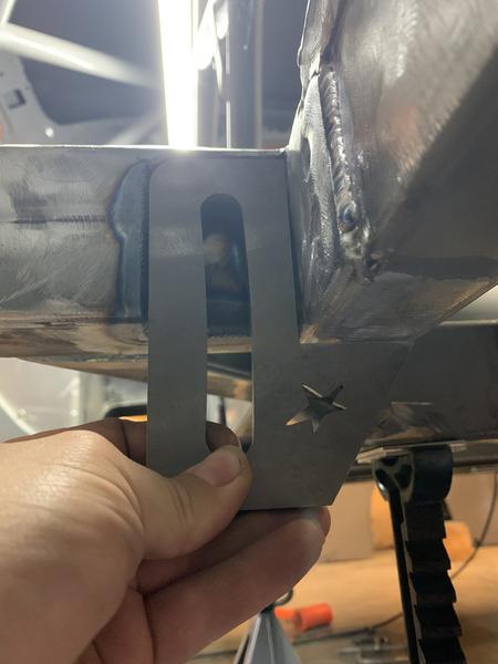
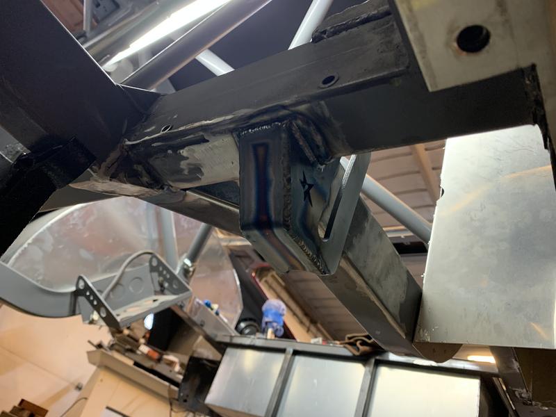
Something I just noticed in the picture that's worth calling out - If you follow the bent floor mounting flange forward, what looks like right underneath the drivers harness eyelet, there's a cutout in the flange and a round nub hanging down. This is a hard jacking point in the middle of the perimeter frame rail. Its also the only thing I have access to when the car is on the ground. Make your lives easier, install reliable jacking points. I only have the two - one in the same place on each side and it allows me to do anything I need.
It hangs down just far enough to where the jack pad wont damage the floor when lifting high, and its small enough (1-3/4) that normal service jack pads will hook around it so the jack can slip off of it. Scary situation at the track a couple years ago - rough and pebbly paddock with smooth frame rails and a floor jack that wasn't allow to roll. Watching the floor jack move on the rail as you go up and down....Not a fan
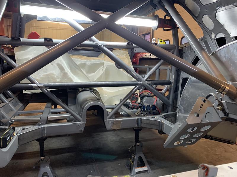
Back to suspension. Now time for the J-bar. The location of the J-bar is dictated by the pinon location. Since the 3rd link mount on the axle needs to be a set distance from the pinion to plant both tires equally, these points need be be as close as you can get them. Always another CL to be laid down, and more plumbs.
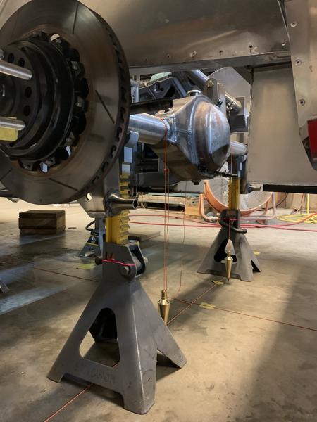
Axle brackets already welded on at this point as they also have specified locations. Axle 3rd link bracket is just tacked for now to check clearances. The height of the third link bracket on the axle wasn't set in stone. Taller is better to a point, but if the room isn't there, it isn't there.
Once alignments were checked it was time to start adding more things to the axle. LCA bracket braces, left watts link point, and ARB brackets.
Call it there for the evening. Part 2 coming up!
Back to the question at the end of the last post - where's the Torque Arm?! At this point I had to make a decision - make mounts to reinstall the TA from the 8.8" on the 9" axle or accept that this is a sign that a different rear suspension setup is meant to be in the car. Can't ignore signs from on high, now can we?
I had my eye on one of Ron's decoupled 3-link setups for a while, so it was time to see what needed to be done for the Cougar to have one. One of the biggest hurdles installing the 3-link was the second "harness bar" that needed to be added. Due to the forces being applied in both acceleration and braking, more support for the J-bar is needed.
Here we go again. Disassemble the assembled
Right around this time, what should arrive?
Soooo many cool things in these boxes. All organized with the respective hardware and Ron had already sent me an email with takeoff points and fabrication guidelines. Back to the second harness bar!
The biggest issue was the 1-1/4" triangulation of the main crossmember. There was no way I was going to risk movement in the chassis at this point so I decided to make my life more difficult and install the 1-3/4" around the 1-1/4". Took a lot of fitting and trimming to achieve the 3-piece tube to make all this happen, but it turned out really well.
Also in the picture are 2x3 tube gussets where the rear rails meets the main crossmember. Gussets like these were originally on the outside, and the lower control arm was on the inside of the frame rail. Ron had specified the control arm be on the outside of the frame rail so this required some changes. I like this configuration much better.
Next were the slotted front LCA mounts. These presented a real challenge. As with most things on the car, the changes I was making and the hardware I was wanting to incorporate wasn't part of the original vision so I had to get creating in some areas. The front LCA mount was one of them.
The pocket in the frame rail that you see had to be made so the the nut, and more importantly, a wrench could be fit in to tighten the LCA bolt. As much of a PITA as this looks, it turned out great. An open end wrench can be fed into the slot with the nut if necessary and its essentially captured during installation and tightening.
Not in these pictures, but just a cool thing Ron does with his DIY packages is include spacers to be used during welding. Bolts in place with an additional shim he supplies to allow for heat distortion and paint after install. I had no problems with double sheer mounting points being too tight after welding.
Something I just noticed in the picture that's worth calling out - If you follow the bent floor mounting flange forward, what looks like right underneath the drivers harness eyelet, there's a cutout in the flange and a round nub hanging down. This is a hard jacking point in the middle of the perimeter frame rail. Its also the only thing I have access to when the car is on the ground. Make your lives easier, install reliable jacking points. I only have the two - one in the same place on each side and it allows me to do anything I need.
It hangs down just far enough to where the jack pad wont damage the floor when lifting high, and its small enough (1-3/4) that normal service jack pads will hook around it so the jack can slip off of it. Scary situation at the track a couple years ago - rough and pebbly paddock with smooth frame rails and a floor jack that wasn't allow to roll. Watching the floor jack move on the rail as you go up and down....Not a fan
Back to suspension. Now time for the J-bar. The location of the J-bar is dictated by the pinon location. Since the 3rd link mount on the axle needs to be a set distance from the pinion to plant both tires equally, these points need be be as close as you can get them. Always another CL to be laid down, and more plumbs.
Axle brackets already welded on at this point as they also have specified locations. Axle 3rd link bracket is just tacked for now to check clearances. The height of the third link bracket on the axle wasn't set in stone. Taller is better to a point, but if the room isn't there, it isn't there.
Once alignments were checked it was time to start adding more things to the axle. LCA bracket braces, left watts link point, and ARB brackets.
Call it there for the evening. Part 2 coming up!
#6
Client Projects & Tips – Muscle Cars / Re: Brakes
Last post by PJ Runnells - May 06, 2026, 04:13 PMSounds good Haven't been able to bleed yet. snowing today in Colorado
#7
Client Projects & Tips – Muscle Cars / Re: Brakes
Last post by Ron Sutton - May 06, 2026, 01:20 PMQuote from: PJ Runnells on Apr 27, 2026, 07:33 PMOk I haven't power bleed the brakes yet. Iam running stoptech brakes on a 67 fire bird did not think about knock back thanks for the information I will definitely check into that. Thank you.
Scot is spot on about knock back. I don't "think" you're experiencing knock back in the StopTech calipers, as I designed those with 6# of anti-knock back spring rate on each piston. But it's still possible. Power bleed the master first. Then run it & see.
#8
Client Projects & Tips – Tube Chassis / Re: Scope creep '69 Cougar
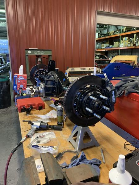
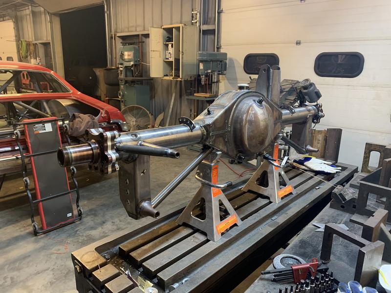
Last post by Ron Sutton - May 06, 2026, 01:17 PMI recognize those Track-Star front hubs!
Great job on the floater & brake caliper brackets.
Great job on the floater & brake caliper brackets.
#9
Front Suspension & Steering Geometry for Track & Racing / Re: Missing some steering feel...
Last post by Ron Sutton - May 06, 2026, 01:14 PMQuote from: Mark Sawatsky on Apr 25, 2026, 10:41 AMI have double wishbone front suspension, rack and pinion steering, KPI is 11 degrees and caster is 5 degrees, tires are 315/30-18 and toe is 1/8 total toe in. The steering is way too light and I have tried an adjustable flow control valve on the power steering and it worked great on the road but made parallel parking impossible. Should I just increase caster to get some steering feel back?
Apologies the site was down. Got hacked. All good now.
You are absolutely correct in that caster will increase steering feel. Plus with 11° of KPI angle, I suspect you're seeing the inside front tire camber inward alot, reducing your inside tire's contact patch. I believe if you bump the caster up to 10-12°, you'll see the inside front tire keeping a better, more full contact patch when turning. Especially on tight corners.
Assuming you have the outside front tire working optimally right now, you'll need to reduce your static camber with the additional caster, to keep the outside front tire contact pact happy.
On a different note, if we reduce the scrub radius on race cars with low caster, the "feel" in the steering reduces. When we increase the caster, the feel comes back, AND we now have the absolute best tire contact patch & overall front grip. In my experience, low scrub radius & high caster go hand-in-hand to creates the best overall front grip.
#10
Client Projects & Tips – Muscle Cars / Re: Brakes
Last post by PJ Runnells - Apr 27, 2026, 07:33 PMOk I haven't power bleed the brakes yet. Iam running stoptech brakes on a 67 fire bird did not think about knock back thanks for the information I will definitely check into that. Thank you.