
Recent posts
#41
Designing & Tuning Aerodynamics for Track & Racing / Designing & Tuning Aerodynamic...
Last post by Ron Sutton - Apr 15, 2026, 12:15 PM Designing & Tuning Aerodynamics for Track Cars & Road Racing
Aerodynamics is a complex subject, and while we may not all become experts at it, that doesn't mean we can't benefit significantly from the parts we do understand. So don't feel like you have to be an
engineer or aerodynamicist to learn & use aerodynamic concepts, aids & features. I have aerodynamic knowledge & experience ... but I am not an engineer or aerodynamicist. I design winning race cars utilizing aerodynamic features on an ongoing basis.
Mechanical Grip:
Most of us understand how to achieve "mechanical grip" through our choice of springs, sway bars, shocks, tires and tuning settings of the front & rear suspension geometries. What we do with these mechanical tuning tools can increase or decrease grip on the tires.
Aerodynamic Grip:
A little more advanced is understanding how changing airflow, decreasing lift & increasing downforce can add grip to the car. There are a lot of tools we'll discuss. They will be new to some of you & old
hat for others. My goal with this thread is to share what I know, as limited as it is, and open discussion on how we can improve our Road Race & Track cars' aerodynamic grip.
Both:
Because when you combine Mechanical Grip & Aerodynamic Grip ... now you've got a fast, drivable Road Race or Track Car. That is our goal here ... to add aero grip to our mechanical grip. We should not try to use aerodynamics as a band-aid for a poor handling car. We should add them together for an optimum handling, class winning, kick in the pants to drive, safe, Track Car.
Where allowed by rules professional race teams run wings or spoilers in the rear, splitters, air dams or spoilers up front, flat bottom belly pans & diffusers underneath, ground effects or side splitters on
the rockers, spill plates wherever possible & smooth, undisturbed body design ... all to go faster. There is no need to debate if aerodynamics works in this day & age. Aerodynamics starts to have a measurable effect at speeds of 50 mph & above.
Properly utilizing aerodynamic knowledge, methods & aids can make your car faster on track, regardless of the car's weight or power. Professional race teams, and the top sportsman race teams, embrace aerodynamics & maximize the use of aerodynamic methods & aids. But for most sportsman Road Racers & Track Cars, aerodynamics is an afterthought & underutilized. I find aero aids that increase downforce or decrease lift to be cheap way to add grip & "safe speed" to the car ... with more car stability & safety.
For aerodynamics, the 4 major ingredients are:
1. Force
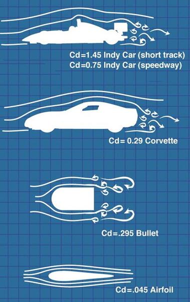
2. Drag
3. Turbulence
4. Structure Design
Reducing drag is important to top speeds. Achieving downforce is important to handling.
If we're running Daytona or Bonneville ... we'll put reducing drag as a priority over downforce. But in Road Race & Track Cars ... downforce is king. F1 cars & Indy Cars in road course trim have horrible Coefficient of Drag numbers. But they have awesome downforce, and that is the key to more tire grip, higher cornering speeds & quicker lap times. There are some things you can do that will both decrease drag & increase downforce ... and many other things where you must choose one or the other. Our priority needs to be downforce.
We care about three variations of "aero force" in Track Cars:
downforce, lift & side force. Every object travelling through air creates either lift, side force or downforce. In the wind tunnel, all of these are measured in pounds of force. Downforce is the most common discussed term. It is referring to "force" pushing down on the body of the car, created by the air traveling over the body ... and wings if they are utilized. If we can transfer this force effectively to the chassis, we will be adding force on the tires, therefore increasing the tires' real world grip.
Lift is the opposite of down force. It is referring to "force" pushing up on the underside of the car, created by air traveling underneath the car. Left alone, this force is lifting the car and reducing force on the tires, therefore decreasing the tires' real world grip.
On the track, at speed, downforce is our friend & lift is our enemy. They counteract ... or fight ... each other, but not necessarily evenly. It's not uncommon for a typical passenger car to have 200-300# of downforce from air traveling over the body shape ... and 600-800# of lifting force from air traveling underneath the car ... at high speeds. When you add "gross lift" & "gross downforce" numbers, you end up with the "net lift or downforce" number.
We care about the total, but knowing how they look front & rear is critical too. If we have a car with:
• 150# of downforce on the front
• 75# of downforce on the rear
• 400# of lift in the front
• 200# of lift in the rear
• We end up with a net lift of 250# in the front & a net lift of 125# in the rear.
This is a "floaty" car overall ... but the front being light is the biggest danger. This may seem like a small amount to some people but, at high speeds on track, I assure you the effect is not small. In this
example, we've lost 375# worth of tire grip. On a 3200# car, that's 8.5% less grip ... most off the front tires.
It should be obvious that just adding a rear spoiler is NOT the end all solution to this problem outlined above. Yes, adding downforce front & rear can be part of the solution. But the smart place to start is reducing the lift ... then look at adding downforce ... as a package solution. A big key to good aero is to reduce the amount of air getting under the car in the first place ... and getting what does go under the
car out as quickly & smoothly as possible.
What you really care about is the net downforce number.
If we worked on this same car & did nothing to increase downforce ... but did reduce the amount of air getting under the car ... and helped the air that did to exit well. We could easily achieve:
• 150# of downforce on the front axle
• 75# of downforce on the rear axle
• 100# of lift in the front
• 50# of lift in the rear
• We end up with a net downforce of 50# in the front & a net downforce of 25# in the rear.
• This is a gain of 450# of downforce.
• That is a LOT of additional tire grip.
Of course, adding some downforce to go with that reduction in lift, would be even better. What does this added downforce do for your Road Race or Track Car?
• Add grip to the tires
• Increase car control & safety
• Increase the speed capabilities the car can safely run at
• And if balanced, helps increase cornering speeds
A key component of aero downforce is "aero balance". Before the COT & Gen 6 cars in NASCAR, teams had a pretty wide area to work in with body design & placement. Of course they did a ton of
work to reduce undercar air & a lot of shaping to create downforce on the body. When you look at a car body, you may say "where is the downforce at on the body?" If it's done right ... it's all over. There is downforce on the hood & front fenders, windshield, roof back glass & deck lid. After testing, the wind tunnel operators may say we have 1260# of net down force with this body shape.
But the downforce is not exactly even. At that time, NASCAR allowed the teams up to 10" of fore & aft range in mounting the bodies. So, for short tracks that were challenging to get & keep the car turning in the corners ... the teams would mount the bodies farther forward on the chassis to place more downforce on the front tires. At 1.5-2 mile super speedways where turning is easier, and rear grip is important, the teams would mount the bodies farther back on the chassis to place more downforce on the rear tires.
A tidbit of trivia for you NASCAR fans: When NASCAR would step in & change the rear spoiler rule ... say from 6.5" to 5" ... this messed up the aero balance so much, that teams had to cut off the bodies, throw them away & start over. Today, this is not the case, as the body rules have been tightened up a zillion miles compared to just 10-20 years ago.
Side force is not talked about much outside of professional oval track teams. But it is, or can be, a big deal. Side force is referring to "force" pushing on the side of the car ... or wing in some cases ... when the car is in a state of yaw. When a car enters the corner ... and continues through the corner ... the body on the outside of the corner is pushing through the air ... similar to how the front end pushes through the air in a straight line. The opportunity for side force is greatest at initial corner turn in and reduces as the car gets to the middle of the corner.
This "side force" can help hold the car on the line at higher speeds. It acts like a tire grip increase. The air pushing on the outside of the car is countering ... to a degree ... the centrifugal forces that want to make the car slide off track. Side force can also be utilized more on one end of the car to help balance the handling.
In bodied cars, the shape of the front fenders can be designed to "catch" more air ... to help the car turn into the corner better. In the NASCAR Modifieds we run on the West Coast, with 52-54% rear weight
bias, being loose on corner entry is a challenge. We designed our cars' bodies & the structure behind them on to achieve 65# of side force at the rear quarter fenders. This allowed our cars to be driven in 6-8' deeper without getting loose on entry. Besides the lap times being quicker, that 6-8' often meant the difference between making a pass or not.
Side force is most obvious on winged sprint cars. The veteran sprint car racers will tell you the "side boards" on the wing are more important than the wing surface. They want both side force & downforce, but the side boards aren't just along for the ride to "help" the wing surface. The side boards play their own critical role in cornering performance. The aero side force is so strong in winged sprint cars, they can carry much higher cornering speeds around a quarter mile dirt track than any other car can on pavement ... unless the pavement car also has large side boards.
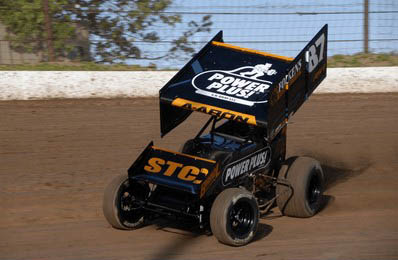
The side force is so strong on winged dirt sprint cars ... the car rolls the opposite direction when cornering. Yes ... the car rolls to the inside of the corner, not the outside. It's not a little bit either. All the modern sprint car chassis have the inside frame rail raised 1" ... so it doesn't bottom out on the ground in the corners.
If the body rules are lax or have loopholes, a creative body builder can give the race team a serious advantage. The images below show what is called a NASCAR "Twisted Sister" body. It creates some good sideforce when it is in yaw (turning left). That same design can be mirrored on the other side for turning left & right on road courses.
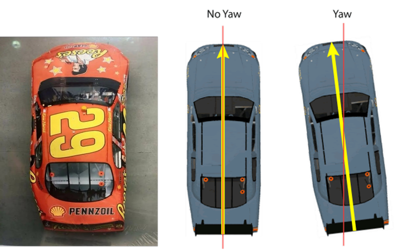
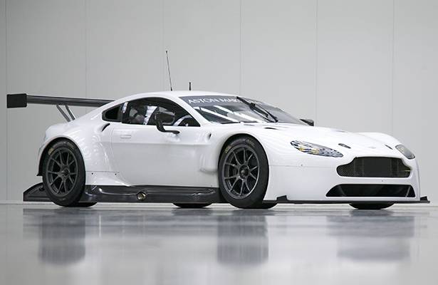
You see this in all kinds of road race bodywork. Here , they're putting side force into the rear fender area:
#42
RSRT Product - Packing List & Instructions / Warrior Rear Frame Wing Mount ...
Last post by Ron Sutton - Apr 14, 2026, 04:56 PMIf you click on any document below, it will open in Post Images.
Once you're in Post Images, you can ...
* Download the document from there.
* Zoom in by Clicking the Zoom button.
* Or, click on the document again, it will zoom to full size on your screen.
* Once the document is full size, you can print it from there as well, by pressing CTRL & P at the same time.
Please pay attention to the part #s in the upper right box of each form. They are different.
#43
RSRT Product - Packing List & Instructions / Warrior Upper & Lower Radiator...
Last post by Ron Sutton - Apr 14, 2026, 04:54 PMIf you click on any document below, it will open in Post Images.
Once you're in Post Images, you can ...
* Download the document from there.
* Zoom in by Clicking the Zoom button.
* Or, click on the document again, it will zoom to full size on your screen.
* Once the document is full size, you can print it from there as well, by pressing CTRL & P at the same time.
Please pay attention to the part #s in the upper right box of each form. They are different.
#44
RSRT Product - Packing List & Instructions / Warrior Transmission Crossmemb...
Last post by Ron Sutton - Apr 14, 2026, 04:53 PMIf you click on any document below, it will open in Post Images.
Once you're in Post Images, you can ...
* Download the document from there.
* Zoom in by Clicking the Zoom button.
* Or, click on the document again, it will zoom to full size on your screen.
* Once the document is full size, you can print it from there as well, by pressing CTRL & P at the same time.
Please pay attention to the part #s in the upper right box of each form. They are different.
#45
RSRT Product - Packing List & Instructions / Warrior Motor Plate & Mid Moun...
Last post by Ron Sutton - Apr 14, 2026, 04:52 PMIf you click on any document below, it will open in Post Images.
Once you're in Post Images, you can ...
* Download the document from there.
* Zoom in by Clicking the Zoom button.
* Or, click on the document again, it will zoom to full size on your screen.
* Once the document is full size, you can print it from there as well, by pressing CTRL & P at the same time.
Please pay attention to the part #s in the upper right box of each form. They are different.
#46
RSRT Product - Packing List & Instructions / Warrior Dual Filter Mount & Ha...
Last post by Ron Sutton - Apr 14, 2026, 04:51 PMIf you click on any document below, it will open in Post Images.
Once you're in Post Images, you can ...
* Download the document from there.
* Zoom in by Clicking the Zoom button.
* Or, click on the document again, it will zoom to full size on your screen.
* Once the document is full size, you can print it from there as well, by pressing CTRL & P at the same time.
Please pay attention to the part #s in the upper right box of each form. They are different.
#47
RSRT Product - Packing List & Instructions / Road Race Seat & Harness Mount...
Last post by Ron Sutton - Apr 14, 2026, 04:49 PMIf you click on any document below, it will open in Post Images.
Once you're in Post Images, you can ...
* Download the document from there.
* Zoom in by Clicking the Zoom button.
* Or, click on the document again, it will zoom to full size on your screen.
* Once the document is full size, you can print it from there as well, by pressing CTRL & P at the same time.
Please pay attention to the part #s in the upper right box of each form. They are different.
#48
RSRT Product - Packing List & Instructions / Warrior Intermediate Steering ...
Last post by Ron Sutton - Apr 14, 2026, 04:47 PMIf you click on any document below, it will open in Post Images.
Once you're in Post Images, you can ...
* Download the document from there.
* Zoom in by Clicking the Zoom button.
* Or, click on the document again, it will zoom to full size on your screen.
* Once the document is full size, you can print it from there as well, by pressing CTRL & P at the same time.
Please pay attention to the part #s in the upper right box of each form. They are different.
#49
RSRT Product - Packing List & Instructions / Wilwood Rear Brakes for Floate...
Last post by Ron Sutton - Apr 14, 2026, 04:46 PMIf you click on any document below, it will open in Post Images.
Once you're in Post Images, you can ...
* Download the document from there.
* Zoom in by Clicking the Zoom button.
* Or, click on the document again, it will zoom to full size on your screen.
* Once the document is full size, you can print it from there as well, by pressing CTRL & P at the same time.
Please pay attention to the part #s in the upper right box of each form. They are different.
#50
RSRT Product - Packing List & Instructions / Wilwood Front Brakes for Track...
Last post by Ron Sutton - Apr 14, 2026, 04:45 PMIf you click on any document below, it will open in Post Images.
Once you're in Post Images, you can ...
* Download the document from there.
* Zoom in by Clicking the Zoom button.
* Or, click on the document again, it will zoom to full size on your screen.
* Once the document is full size, you can print it from there as well, by pressing CTRL & P at the same time.
Please pay attention to the part #s in the upper right box of each form. They are different.