

Recent posts
#51
RSRT Product - Packing List & Instructions / Race-Warrior 5" Watts Link Kit...
Last post by Ron Sutton - Apr 14, 2026, 04:30 PMIf you click on any document below, it will open in Post Images.
Once you're in Post Images, you can ...
* Download the document from there.
* Zoom in by Clicking the Zoom button.
* Or, click on the document again, it will zoom to full size on your screen.
* Once the document is full size, you can print it from there as well, by pressing CTRL & P at the same time.
Please pay attention to the part #s in the upper right box of each form. They are different.


When complete, it should look like the illustration below:

Once you're in Post Images, you can ...
* Download the document from there.
* Zoom in by Clicking the Zoom button.
* Or, click on the document again, it will zoom to full size on your screen.
* Once the document is full size, you can print it from there as well, by pressing CTRL & P at the same time.
Please pay attention to the part #s in the upper right box of each form. They are different.
When complete, it should look like the illustration below:
#52
RSRT Product - Packing List & Instructions / BYO GT Watts Link Kits
Last post by Ron Sutton - Apr 14, 2026, 04:12 PMIf you click on any document below, it will open in Post Images.
Once you're in Post Images, you can ...
* Download the document from there.
* Zoom in by Clicking the Zoom button.
* Or, click on the document again, it will zoom to full size on your screen.
* Once the document is full size, you can print it from there as well, by pressing CTRL & P at the same time.
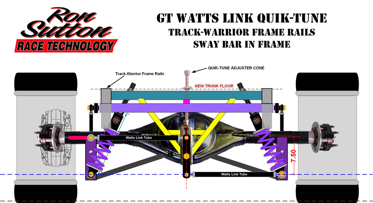
Please pay attention to the part #s in the upper right box of each form. They are different.


When Assembled, it should look like this illustration:
Once you're in Post Images, you can ...
* Download the document from there.
* Zoom in by Clicking the Zoom button.
* Or, click on the document again, it will zoom to full size on your screen.
* Once the document is full size, you can print it from there as well, by pressing CTRL & P at the same time.
Please pay attention to the part #s in the upper right box of each form. They are different.
When Assembled, it should look like this illustration:
#53
RSRT Product - Packing List & Instructions / Quik-Tune Top Link J-Bar & Har...
Last post by Ron Sutton - Apr 14, 2026, 04:08 PMIf you click on any document below, it will open in Post Images.
Once you're in Post Images, you can ...
* Download the document from there.
* Zoom in by Clicking the Zoom button.
* Or, click on the document again, it will zoom to full size on your screen.
* Once the document is full size, you can print it from there as well, by pressing CTRL & P at the same time.
Please pay attention to the part #s in the upper right box of each form. They are different.


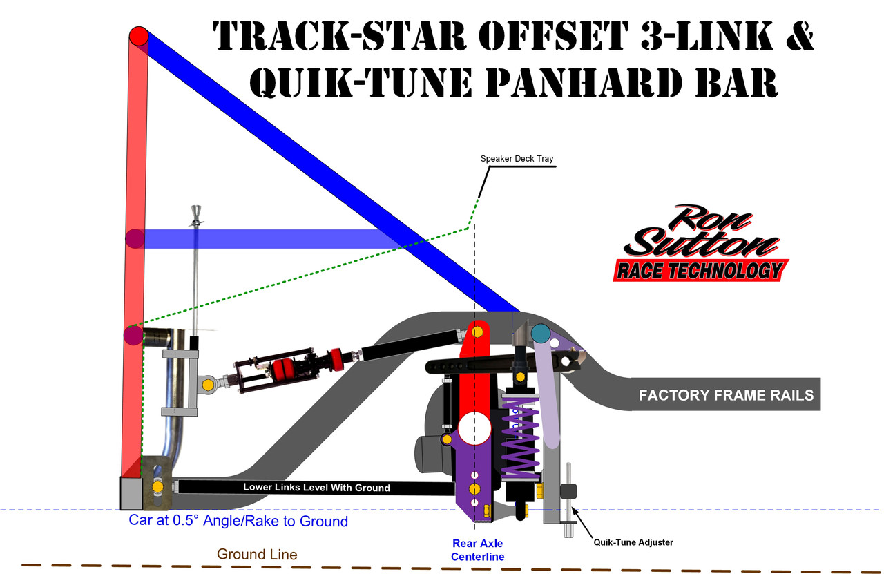
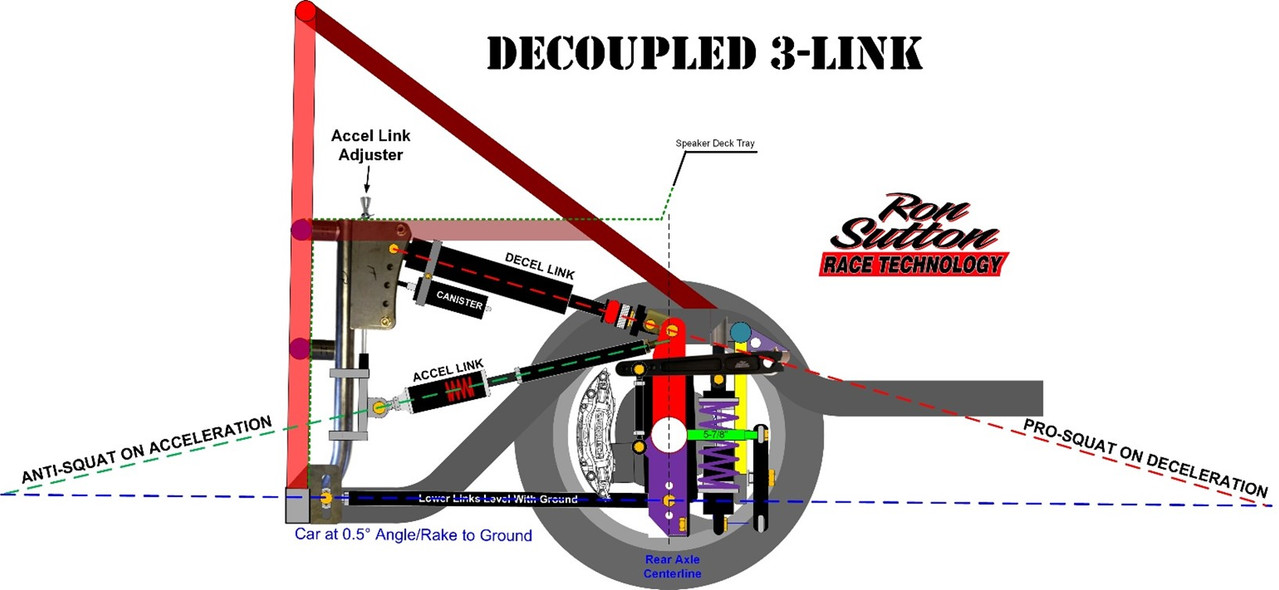
When Assembled, the J-Bar & Quik-Tune Adjuster should look like this illustration:
* UNLESS, you want to run the J-Bar full length for a Decoupled 3-Link. Then it should look like the second illustration below:
Once you're in Post Images, you can ...
* Download the document from there.
* Zoom in by Clicking the Zoom button.
* Or, click on the document again, it will zoom to full size on your screen.
* Once the document is full size, you can print it from there as well, by pressing CTRL & P at the same time.
Please pay attention to the part #s in the upper right box of each form. They are different.
When Assembled, the J-Bar & Quik-Tune Adjuster should look like this illustration:
* UNLESS, you want to run the J-Bar full length for a Decoupled 3-Link. Then it should look like the second illustration below:
#54
RSRT Product - Packing List & Instructions / ZXR3 3-Link - Top Link Mount &...
Last post by Ron Sutton - Apr 14, 2026, 03:47 PMIf you click on any document below, it will open in Post Images.
Once you're in Post Images, you can ...
* Download the document from there.
* Zoom in by Clicking the Zoom button.
* Or, click on the document again, it will zoom to full size on your screen.
* Once the document is full size, you can print it from there as well, by pressing CTRL & P at the same time.
Please pay attention to the part #s in the upper right box of each form. They are different.
#55
RSRT Product - Packing List & Instructions / Decoupled 3-Link J-Bar & Decel...
Last post by Ron Sutton - Apr 14, 2026, 03:44 PMIf you click on any document below, it will open in Post Images.
Once you're in Post Images, you can ...
* Download the document from there.
* Zoom in by Clicking the Zoom button.
* Or, click on the document again, it will zoom to full size on your screen.
* Once the document is full size, you can print it from there as well, by pressing CTRL & P at the same time.
Please pay attention to the part #s in the upper right box of each form. They are different.
#56
RSRT Product - Packing List & Instructions / Torque Arm Decoupled Decel Lin...
Last post by Ron Sutton - Apr 14, 2026, 03:36 PMIf you click on any document below, it will open in Post Images.
Once you're in Post Images, you can ...
* Download the document from there.
* Zoom in by Clicking the Zoom button.
* Or, click on the document again, it will zoom to full size on your screen.
* Once the document is full size, you can print it from there as well, by pressing CTRL & P at the same time.
This is the front Decoupled Torque Arm Decel Mount Kit for Full Bodied Cars - NOT Tube Chassis Warriors
#57
RSRT Product - Packing List & Instructions / Torque Arm Crossmember Flange ...
Last post by Ron Sutton - Apr 14, 2026, 03:33 PMIf you click on any document below, it will open in Post Images.
Once you're in Post Images, you can ...
* Download the document from there.
* Zoom in by Clicking the Zoom button.
* Or, click on the document again, it will zoom to full size on your screen.
* Once the document is full size, you can print it from there as well, by pressing CTRL & P at the same time.
Please pay attention to the part #s in the upper right box of each form. They are different.
#58
RSRT Product - Packing List & Instructions / BYO Lower Link Tubes - Kits
Last post by Ron Sutton - Apr 14, 2026, 03:32 PMIf you click on any document below, it will open in Post Images.
Once you're in Post Images, you can ...
* Download the document from there.
* Zoom in by Clicking the Zoom button.
* Or, click on the document again, it will zoom to full size on your screen.
* Once the document is full size, you can print it from there as well, by pressing CTRL & P at the same time.
Please pay attention to the part #s in the upper right box of each form. They are different.
#59
RSRT Product - Packing List & Instructions / Rear Suspension Lower Link Mou...
Last post by Ron Sutton - Apr 14, 2026, 03:30 PMIf you click on any document below, it will open in Post Images.
Once you're in Post Images, you can ...
* Download the document from there.
* Zoom in by Clicking the Zoom button.
* Or, click on the document again, it will zoom to full size on your screen.
* Once the document is full size, you can print it from there as well, by pressing CTRL & P at the same time.
Please pay attention to the part #s in the upper right box of each form. They are different.


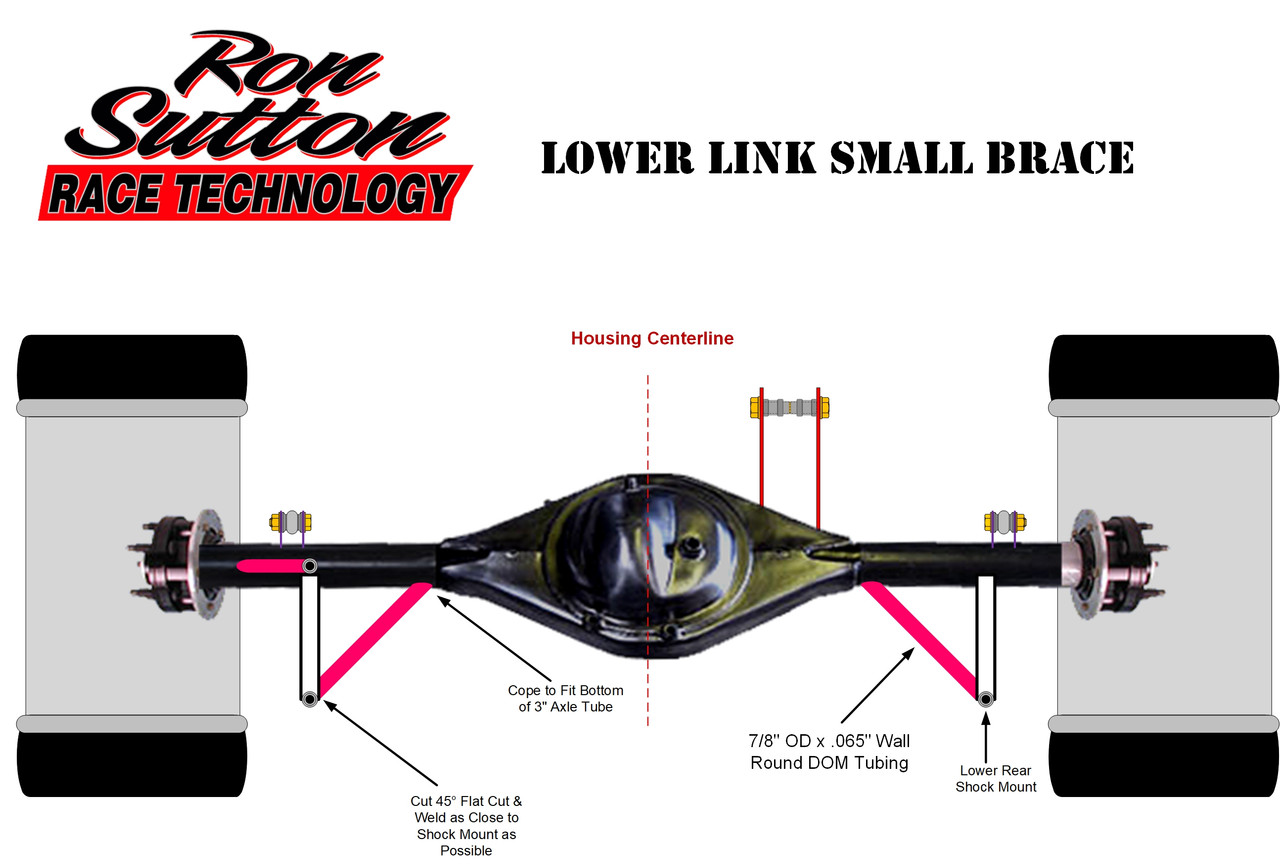
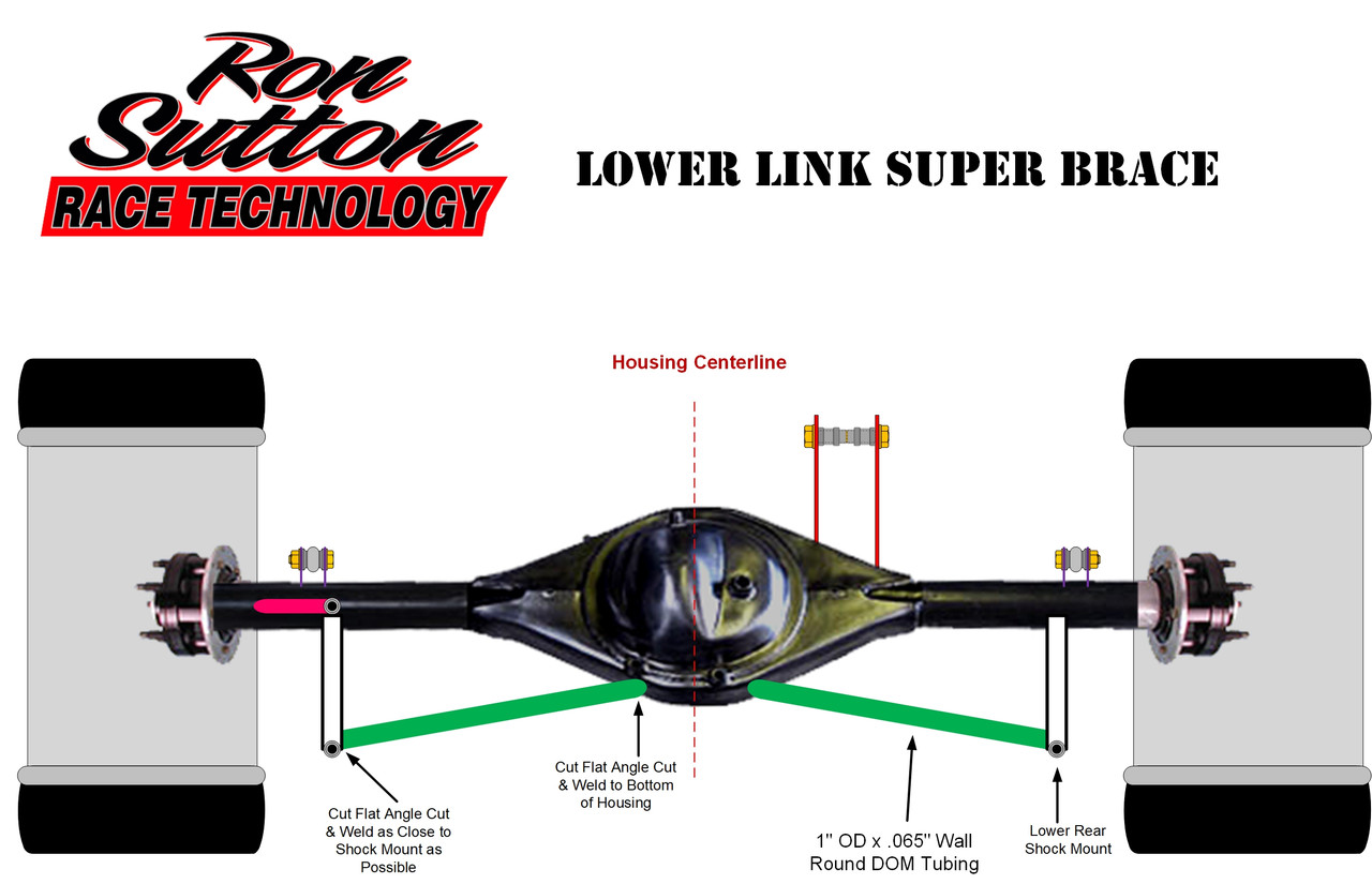
If your rear suspension will have coil-overs at more than a 12° angle ... AND/OR ... you're mounting our 7.5" GT Watt link with the lower tube mounting to the back of the Passenger Side Shock Mount ... you will want to add tubing braces from the rear axle housing to the mounts. See images below.
Once you're in Post Images, you can ...
* Download the document from there.
* Zoom in by Clicking the Zoom button.
* Or, click on the document again, it will zoom to full size on your screen.
* Once the document is full size, you can print it from there as well, by pressing CTRL & P at the same time.
Please pay attention to the part #s in the upper right box of each form. They are different.
If your rear suspension will have coil-overs at more than a 12° angle ... AND/OR ... you're mounting our 7.5" GT Watt link with the lower tube mounting to the back of the Passenger Side Shock Mount ... you will want to add tubing braces from the rear axle housing to the mounts. See images below.
#60
RSRT Product - Packing List & Instructions / Front Sway Bar Mount Kits
Last post by Ron Sutton - Apr 14, 2026, 02:57 PMIf you click on any document below, it will open in Post Images.
Once you're in Post Images, you can ...
* Download the document from there.
* Zoom in by Clicking the Zoom button.
* Or, click on the document again, it will zoom to full size on your screen.
* Once the document is full size, you can print it from there as well, by pressing CTRL & P at the same time.
Please pay attention to the part #s in the upper right box of each form. They are different.